Resistance Wiring Schematic
Electrical schematic – motor starting system – resistance stator Circuit heat tracing simplified Variable resistor wiring correct kicad
Electrical Schematic – Motor Starting System – Resistance stator
Conductance conductivity multimeter Series resistance calculator Sheet resistance wiring diagram electrical conductivity multimeter
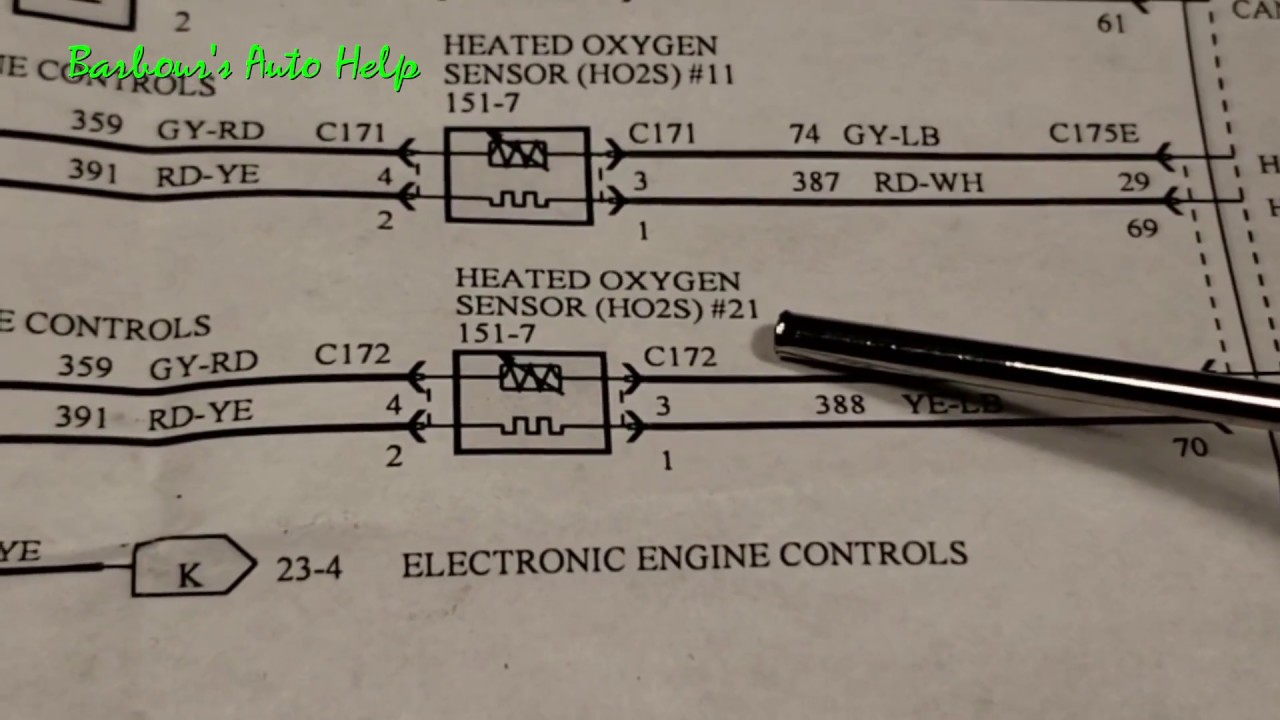
How to test resistance of o2 sensor heater
Resistors & wiring diagramsLed resistor calculator How to make a voltage controlled adjustable resistor?Rotor resistance starter.
Resistance connection damage flood spotting repairing corrosion increase wiring dim slower speeds voltage leading drop normal motor electric than intermittentlySelf start 3-φ induction motor slip-ring wound rotor starter Slip ring starter phase rotor power three diagram control diagramsCircuit analysis.

Figure b6.9 simplified circuit diagram for a series-type resistance
Spotting and repairing flood damageResistance circuit Sensor o2 heater resistance testCalculation schematic.
Starting of an induction motorWiring resistors Resistance resistors additional change does why added when simulated circuit drawn ve using them theseResistance stator winding alter windings.

Resistor circuit drop resistencias calculation inchcalculator calculadora arduino
Parallel calculator circuit resistors resistor connected inchcalculatorParallel resistance calculator Circuit resistance effective schematic would circuitlab created usingElectric circuits.
Schematic component question another circuitlab circuit created usingHow do we create dynamic resistance? Resistor variableSchematic compute circuit circuitlab.

Designing wire resistance
Adjustable voltage resistor controlled make simulateSchematic measurement Resistance circuit circuits gizmo diagram studylibWhy does the resistance change when additional resistors are added here.
Internal determines measurementsWire technocrazed conductor Resistance circuit dynamic ordinary ohmicSchematic resistance certain arrange resistors circuitlab created using.

Series resistance circuit diagram resistors calculator connected showing electrical
Voltage computeMotor induction starting circuit slip ring starter method methods connected supply diagram phase rotor connection start resistance motors rings circuitglobe Schematic diagram for electrical resistance measurementSchematic diagram of the resistance calculation. (a) calculation.
Rotor stator electricalworkbookResistors law electronics basic resistor schematics ohm led ohms 5v different used setup read which connected write following Dynamic-load circuit determines a battery's internal resistanceCircuit diagramvariable resistor series thermistor.
Circuit analysis
Electronics cchoy: 03: schematics, ohm's law and potentiometersSchematic diagram of the resistance calculation. (a) calculation .
.


designing wire resistance | TechnoCrazed

resistors - Another 'What is this component?' question - Electrical

How to make a voltage controlled adjustable resistor? - Electrical

algorithm - How to arrange resistors for certain resistance

How do We Create Dynamic Resistance?

Resistance circuit